Installing Solar on a Unique I-Beam Roof Structure
ABC Solar has a long history of installing solar in unique locations with special materials. This I-beam “roof” over a pool is a great example: the roof structure is steel, the span is large, and the solar array becomes both power plant and architectural element.
Structure first
On steel, the “roof” is the frame. Loads, fasteners, and corrosion strategy must be planned up front.
Bonding matters
Steel + racking + modules must be bonded/grounded correctly so the system is safe and code-clean.
Design for the space
Pool decks, ladders, and walkways require smart staging and a clean final look.
The roof structure: steel I-beams over a pool
This “roof” used to house a cover over the pool. ABC Solar converted the structure into a solar mounting platform.
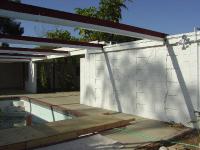
1) Unistrut Mounting Structure (the sub-structure)
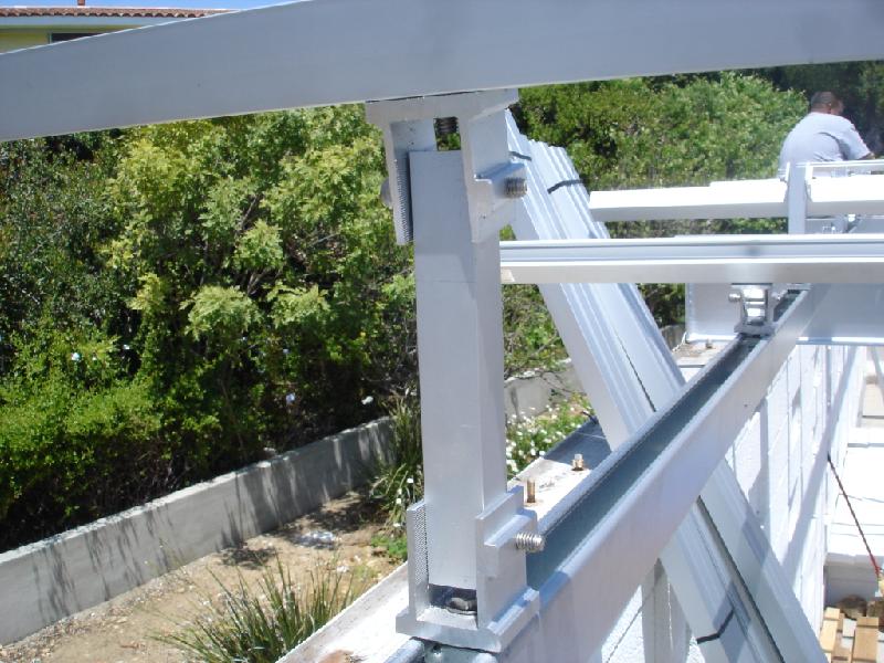
The first design consideration was spanning 11 feet and 10 feet between I-beams. ABC Solar used 20' Unistrut galvanized steel beams to create a sub-structure that could then host standard solar mounting gear.
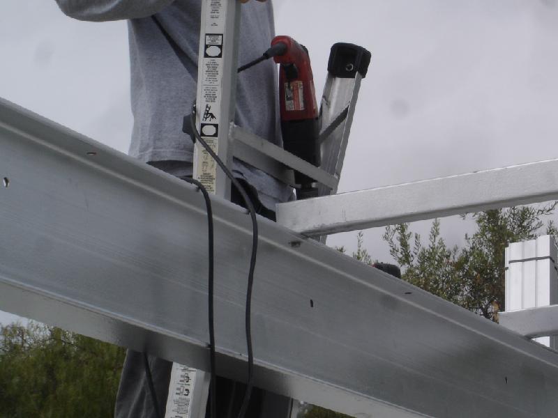

2) No Waterproofing Needed (because it’s not a roof membrane)
This structure required no waterproofing considerations because there is no conventional roof surface beneath the array. That shifts the engineering focus toward: structural load paths, hardware integrity, and corrosion strategy.
The second design consideration was the spacing between rows to prevent row-to-row shading during winter sun angles.
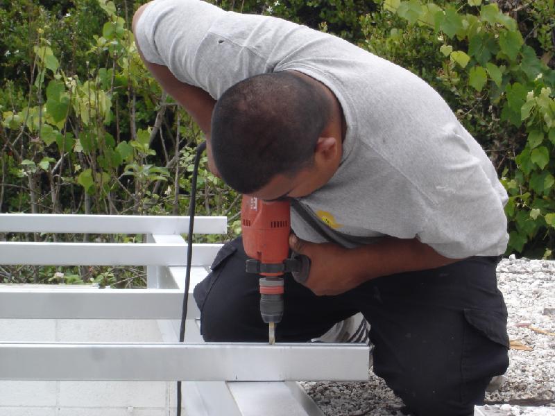
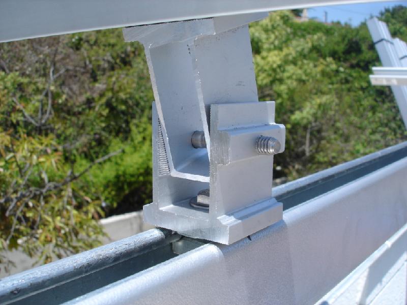
3) Solar Rails Attach to Solar Mounts
Rails are laid along the mounts to check distance and straightness. The number of panels is calculated by width/height depending on portrait vs landscape orientation.
For layout purposes (as documented in the original notes), we may treat certain modules slightly larger than their actual size to account for mounting parts. Rails are drilled above each mount and attached with washer and bolt.
4) Solar Panels Are Attached (array becomes the roof)
Once the rail system is straight and repeatable, modules are mounted and wiring is dressed. On a structure like this, the array essentially becomes a shading canopy over the pool area.
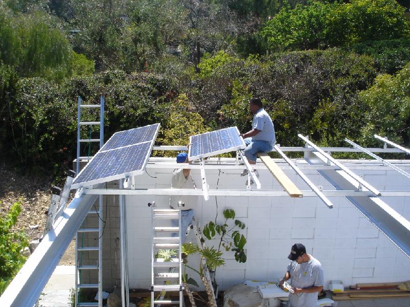
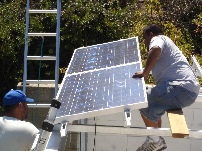
Project story: Brill Glass & Steel Solar Estate
4.28 kW grid-tie solar plus 1 kW pool circulation. A modern steel-and-glass flat-roofed “pool house” designed in 1955 was the location for an extensive solar installation by ABC Solar (2007).
The solar installation is on the south-west corner of the property, with an array of 32 Mitsubishi 165W panels in two rows, mounted along the steel I-beams that act as an open-air cover for the pool.
The panels are pointed south at a 15° tilt to achieve strong summer production and to allow the panels to self-clean when it rains. Six panels are routed to a DC solar-powered pool pump that handles circulation and filtration for the pool. The 1.5 HP DC pump can do 60 to 90 gallons per minute during its solar production day.
Unique roof checklist (what we verify before we build)
When the structure is custom, the checklist gets tighter—not looser.
Structural load path
We verify how loads transfer through steel members, attachment points, and bracing (and coordinate engineering as needed).
Corrosion strategy
Galvanized steel, stainless fasteners, isolation where needed—compatibility prevents ugly hardware and long-term issues.
Bonding & grounding
Steel structures require clean bonding/grounding paths. We keep it code-correct and inspection-friendly.
Row spacing & shade
Unique roofs often have unique shade profiles. We prevent winter self-shading and avoid “surprise” performance loss.
Safe access & service
Pools, decks, and ladders demand safe staging now—and practical service access later.
Wire protection
Steel edges can chafe. We route and protect wiring so it stays safe, clean, and durable.

First consideration: picking the best roof face
The first consideration for all solar installations is picking the best roof face to use for your system. Factors to consider are shade from trees and chimneys and the conduit run from the panels to the main electrical panel.
Design it right once. Install it clean once. Service it easily forever. CCL#914346